Dual Contouring In 2d In Which Meshes Are Generated
TL;DR
Dual contouring is a handy technique for generating a mesh for volume data such as voxels or distance fields which preserves sharp corners, unlike the more famous marching squares.
Constructive Solid Geometry
Constructive solid geometry (CSG) is a powerful technique for editing shapes. A CSG system gives you three fundamental operations to work with:


Using these three basic operations on primitive shapes (cuboids and spheres) you can create a huge variety of shapes.
Volume Data
When thinking about how to implement CSG the first thing to come to mind is probably something working directly with meshes. You can simply walk along the edges, cut them where they intersect another shape and stitch everything together. This can be made to work but is extremely complex, requires that your initial primitives are meshes (limiting their precision) and in my experience frequently suffers from tricky numerical errors.
An alternative way to achieve CSG is to use volume data. With volume data we don’t represent the primitives with a mesh approximating their shape, instead we directly represent the primitives with a mathematical object which perfectly captures the primitive. CSG operations become simple mathematical operations on their objects. Then once all the CSG is done we need a final step to convert into a useful format (i.e. a mesh).
The way we represent the shapes is with a distance field - this is a field which can be sampled at any position to get back a number which represents the distance from the surface of the shape (a negative value indicating that this point is inside the shape). Of course this does not need to be stored as a big 2D array instead it can be generated on the fly to achieve effectively infinite accuracy with zero memory overhead. For example here’s a circle:
class Circle {
  private readonly Vector2 _center;
  private readonly float _radius;

  float Sample(Vector2 position) {
    return Vector2.Distance(_center, position) - _radius;
  }
}
This very simple class implements the contract I mentioned above - when the position is inside the circle the distance will be negative, when it is outside the circle it will be positive. The only other shape I have implemented so far is a halfplane shape which splits the universe into two halves (inside and outside) - any shape with straight edges can be built using a series of CSG operations on half planes.
Constructive Solid Geometry
We’ve established how shapes will be represented, but how does this actually help with CSG? Recall the three fundamental operations of CSG are Union, intersection and difference:
Implementing these operations with distance fields is trivial. To Union two shapes we just take the minimum value from two fields:
public float SampleDistance(Vector2 position)
{
    return Mathf.Min(
      a.SampleDistance(position),
      b.SampleDistance(position)
    );
}
This creates a new distance field which represents the union of the two fields (named a and b in this example).
Intersection is the max value:
public float SampleDistance(Vector2 position)
{
    return Mathf.Max(
      a.SampleDistance(position),
      b.SampleDistance(position)
    );
}
Difference can actually be built out of other operations. Logically difference is taking all the space where A AND Not(B). Since intersection provides us with an “AND” operation, we can implement subtraction with a variation of intersection:
difference = Intersection(a, Negate(b));
Creating A Mesh
Now that we can do CSG on distance fields we need a way to convert a distance field into a mesh. I’m going to use the following example shape:

This is a good test because it combines smooth curves with sharp corners, the meshing system must be able to gracefully handle both these things. For anyone trying to recreate this example the code to produce this shape is:
var e1 = new Circle(v(0.2f, 0.2f), f(0.05f));
var e2 = new Circle(v(0.2f, 0.8f), f(0.05f));
var m = new Difference(
    new Intersection(
        new Rectangle(v(0.6f, 0.15f), v(0.9f, 0.85f)),
        new Circle(v(0.35f, 0.5f), f(0.5f))
    ),
    new Circle(v(0.25f, 0.5f), f(0.5f))
);
var n = new Rectangle(v(0.4f, 0.45f), v(0.5f, 0.55f));

return Union.Create(e1, e2, m, n);
All the values are defined in the 0 to 1 range and the v (for vector) and f (for float) functions simply take those values and scale them into whatever range you’re really using.
Sampling
A distance field has infinite accuracy since it’s just a mathematical model of a shape. Obviously to convert this into a mesh we’re going to need to sample the field at some points - but where?
Grid Sampling
The obvious approach is just a regular sampling on a grid:
This suffers problems with curves and corners. The curves have been rasterized down to the resolution of the grid and all corners have been snapped to 90 degrees. This could be fixed with a denser grid but that doesn’t scale very well because we’d be sampling and storing a load of points in completely empty space! What we need to do is sample the grid with more detail where the distance field is near zero.
Quadtree Sampling
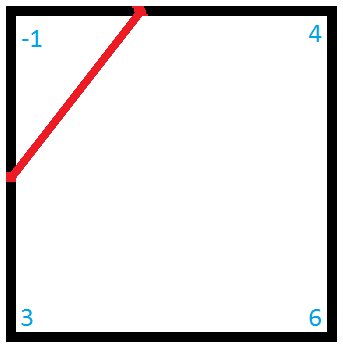
A quadtree is a tree of nodes, each node can contain exactly 4 children which fill in it’s available space. This looks a little bit like this:
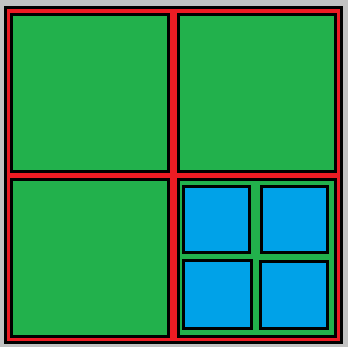
Here are have a quadtree with it’s top level in red, this contains four children in green and one of those contains 4 children in blue.
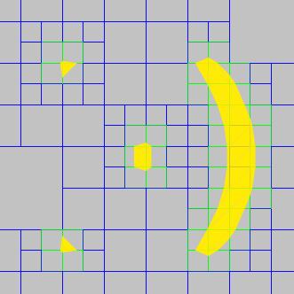
With quadtree sampling we sample the distance field at the corner of each node and then recursively subdivide the nodes which need more detail. This approach is called an “adaptively sampled distance field” and looks a bit like this:
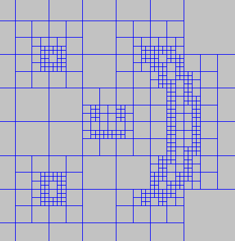
This is much better - the smallest squares here are half the size of the uniform grid sampling (twice as much resolution) but we have less than half the total node count.
This system isn’t without it’s own drawbacks. The most critical question is: how do we decide when a node needs more detail? What we want is to subdivide only nodes which contain the surface of the shape, unfortunately this is (in general) pretty hard to detect just from a distance field. Consider this single quadtree node:
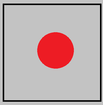
Here we have a very large single quadtree node which contains a small circle in the distance field. Because we only sample the distance field at the corners there’s no way to tell that this node contains the surface of the shape and should be subdivided. To fix this I went back to the source and changed the definition of my distance fields:
public interface IDistanceField
{
    float SampleDistance(Vector2 position);

    bool MayContainIsosurface(Rect rectangle);
}
The “MayContainIsosurface” method take a rectangle and returns a boolean which indicates if the surface of the shape might be within this rectangle. My logic here is that most primitive shapes can trivially determine if a given rectangle contains their surface. Here’s the implementation for my circle class:
public bool MayContainIsosurface(Rect rectangle)
{
    if (!_circle.Overlaps(rectangle))
        return false;

    if (!_circle.Contains(rectangle))
        return false;

    return true;
}
Two very simple checks which exploit the basic geometry primitives I have available in libraries.
With this change to distance fields the problem of which node to subdivide is trivial - just check if the node area may contain the surface of the distance field.
I added an additional optimisation step to the quadtrees after they have finished subdividing. Any particular interior node contains 4 corners points and 5 interior points (the corners of it’s 4 children), if the 5 interior points can all be accurately calculated using a bilinear interpolation of the 4 corner points we can safely discard the leaves because they’re not providing any additional detail.
Making meshes
Now that we have a suitably sampled distance field without horrible memory usage but still preserving detail we need to actually generate some meshes!
Marching Squares
Marching squares is a fairly well known and very simple technique. We simply process each cell completely independently and match it to a lookup table based on the sign at each cell corner. There are sixteen total cases to consider (red indicates inside the shape, i.e. a negative distance):


Here’s the simplest example of marching cubes I can construct:
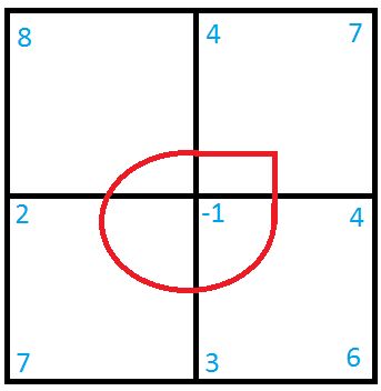
The red circle is the surface of the shape we’re trying to represent. I’ve tagged all the corners with their distance from the surface. Marching cubes looks at each node one at a time so we’ll do the same:
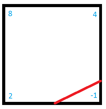
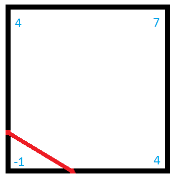
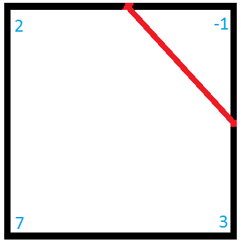
As you can see all we do is work out how far along the edge the surface is (based on a reverse lerp estimate of where zero is), and then place a straight line across the corner to connect these points. The problem here is immediately obvious - any details which are inside the shape (curves or corners) are completely lost. We could fix the curves by sampling with more resolution but that will never fix corners - they will always be slightly rounded unless they lie exactly on a node edge. You can see this problem (exaggerated by a very low detail quadtree) here:
There’s an additional problem not shown here. Because we consider each node independently the points on each node will not match up perfectly - this will leave tiny cracks (which become obvious with very large or very low detail fields, particularly in 3D).
Dual Contouring
Dual contouring solves both of these problems at once by working with the dual graph of the quadtree. The dual of a graph replaces all the faces with vertices, and all edges with perpendicular edges connecting to these new vertices. Here’s an example quadtree with a dual graph drawn in yellow:
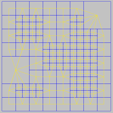
With the dual graph rather than placing vertices along the edges of the nodes we place a single vertex inside each node. If this vertex is placed on top of the sharpest corner in the node then corners will be perfectly preserved (to the limit of the sampling resolution). Placing this vertex is achieved with by minimizing a “Quadratic Error Function” (QEF), this function expresses how far from the surface of the shape a given point is and thus minimizing it naturally places the point on the surface. This is not always perfect because it is possible that there are two corners in a single node and in that case minimizing the QEF will likely place the vertex somewhere between the two.
There are many possible QEFs and techniques for minimizing them. For my simple little test project I used a simple iterative gradient descent however this isn’t perfect as it could get stuck in a local minimum (I hacked a fix for this by subsampling the node to get some extra detail, but this is a very expensive solution).
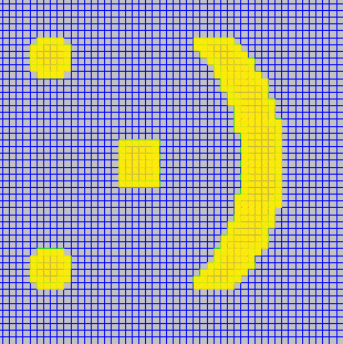
Finally here’s the result of dual contouring on the smiley (using a very coarse grid to push the system to it’s limits):
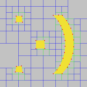
Curves are not improved much over marching squares (that can only really be fixed by higher resolution) but the corners are vastly improved! The sharp corners on the mouth and the nose are in exactly the right positions.