Procedural Generation For Dummies: Half Edge Geometry In Which A Datastructure Is Revealed
Procedural City Generation For Dummies Series
- Procedural Generation For Dummies: Building Footprints
- Procedural Generation For Dummies: Half Edge Geometry
- Procedural Generation For Dummies: Galaxy Generation
- Procedural Generation For Dummies: Lot Subdivision
- Procedural Generation For Dummies
- Procedural Generation For Dummies: Road Generation
My game, Heist, is a cooperative stealth game set in a procedurally generated city. This series of blog posts is an introduction to my approach for rapidly generating entire cities. If you’re interested in following the series as it’s released you can follow me on Twitter, Reddit or Subscribe to my RSS feed
A lot of the code for my game is open source - the code applicable to this article can be found here. Unfortunately it has some closed source dependencies which means you won’t be able to compile it (I hope to fix that soon) but at least you can read along (and criticise my code). I should point out that this code is in a bit of a state of flux at the moment - I’ve just recently started an overhaul of some of its core components - so some of it which is only half overhauled may read a little strangely right now!
Messy Meshes
One thing which I have to deal with all the time in procedural generation is meshes - that is things which can be represented as a set of vertices, edges and faces. They appear in road generation (roads, junctions and blocks), floor plan generation (wall join, walls and rooms) and navmesh generation (faces are walkable areas).
Computational geometry is an infamously tricky subject, so it’s important to have a good set of structures for representing the data you’re working with and a good set of tools to manipulate that data.
Indexed Meshes
Most programmers who have worked with graphics will be familiar with an indexed mesh. This is a very simple structure:
- List of vertices
- List of ( List of indices )
We have a flat list of vertices (positions) in a completely arbitrary order. Each face is a list of indices, the indices of the vertices which make up this face. Our mesh is then a list of faces - a list of list of indices. If we want to specialise to purely graphical meshes then there is an easy optimisation to make here; since we know every face has three sides simply store the indices as one continuous list (with N, N+1 and N+2 as the three corners). However we want to be a little more general than that so in this system a face is any set with three or more vertices.
Here’s an example:
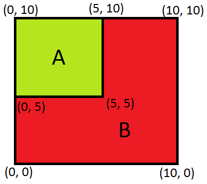
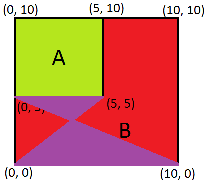
We’ve got two shapes, A and B. Here’s what that would look like in indexed mesh form:
Vertices: [ (0, 0), (10, 0), (10, 10), (5, 10), (0, 10), (0, 5), (5, 5) ]
Faces: [[4, 3, 6, 5], [0, 5, 6, 3, 2, 1]]
The order of the vertices here is totally arbitrary. The indices in each face are stored in clockwise order around the face.
This is simple to build, and simple to enumerate but it doesn’t really offer any good tools to help you build correct geometry. For examples let’s add another face
[0, 6, 5, 1]
As you can see below this face overlaps the other faces, is incorrectly wound (anticlockwise) and is self intersecting! These are all properties which we want to avoid and, if possible, should be impossible to construct.
Half-Edge Meshes
Indexed meshes are a very topographical way of representing a mesh - they contain the information about positions and not really much else. Checking for the three critical properties (winding order, overlapping and self-intersection) would require a series of costly vector operations. With a Half-Edge mesh we keep a lot of the topological information about the mesh around which means that checking all of these properties becomes just a series of pointer lookups and equality comparisons.
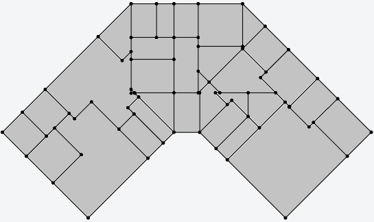
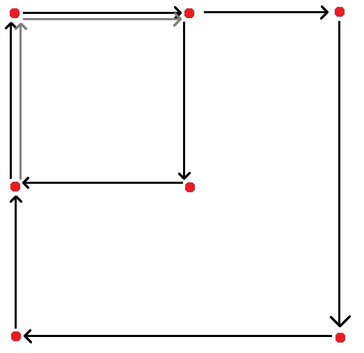
Let’s create the same shape as before, but with a half-edge representation:
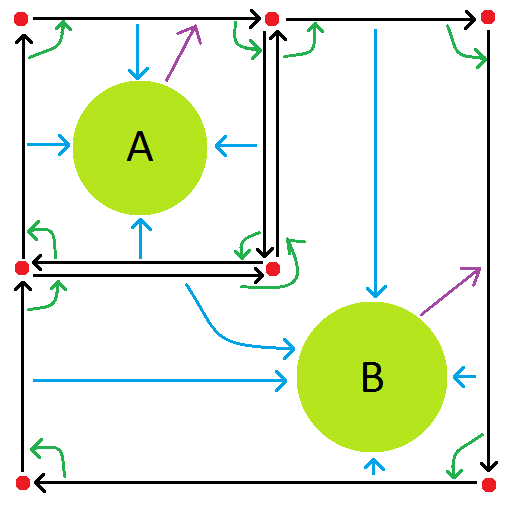
I know this looks complex, but that’s because we’re keeping so much more useful information around! Let’s look through the parts one at a time:
Vertices
These are represented by the red dots in the diagram. A vertex contains two pieces of information:
- Position
- List of edges starting at this vertex
That’s it! You can extend this model to store more per vertex attributes (normals, texture coordinates etc) but I’ve not yet had a use for this.
Half Edges
These are represented by black arrows in the diagram. These are the key part of this structure - every connection between two vertices is a one way edge - hence the name half edge because each complete edge is represented by two one-way halves. A half edge contains 4 pieces of information:
- Sibling Edge (opposite direction edge)
- End Vertex
- Face which this edge borders (possibly null, if there is no such face). This is represented by the blue arrows in the diagram.
- Next edge around the face this edge borders (possibly null, if there is no such face). This is represented by the green arrows in the diagram.
Faces
These are represented by the pale green circles (labelled with the same letters as in the previous diagram). The faces are actually very simple, containing just one single piece of information:
- An arbitrary edge bordering this face
That’s it! With just this information we can answer a lot of useful queries about the mesh and also ensure that those three critical properties (winding order, overlapping and self-intersection) are maintained at all times.
Critical Properties
It may not be entirely obvious how those critical properties are maintained in this system and in fact they can be violated in certain circumstances - but constructing such an invalid mesh is quite difficult and generally as soon as you try to do anything with it the system is going to notice something is broken and immediately throw an exception.
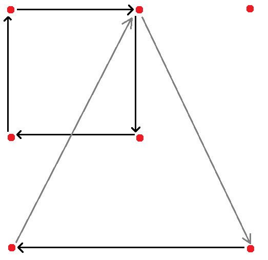
Winding Order
Here’s the example image from before cut down to just show two edges attached to the two faces. If we tried to reverse A (so it was incorrectly wound) it would be impossible - the edge going up along the right hand side of A is already in use. Since an edge can only ever be assigned to one face if we ever find ourselves trying to attach an edge to another face we know we’re trying to construct invalid geometry.
This property can be violated if you construct two completely independent faces (sharing no vertices) - one clockwise, and one anticlockwise. As soon as you try to connect these faces up in any way it will be impossible.
My implementation actually has an additional check to catch invalid winding much earlier than this. When you construct a new mesh object you specify which winding you want. Whenever a new face is constructed it’s winding order is checked (geometrically, by looking at the area of the face and checking if it is negative).
Self Intersection
The right hand face here is clearly broken and this is another example of how it’s sometimes possible to construct broken geometry - that face does not violate any of the invariants of a half edge structure. However if you have a self intersecting shape at least one of the edges must be incorrectly wound (in this case the top right horizontal edge). This means all self intersecting shapes become a subset of the winding problem and are solved in the same way - as soon as you try to connect that incorrect edge to anything else the error will be detected.
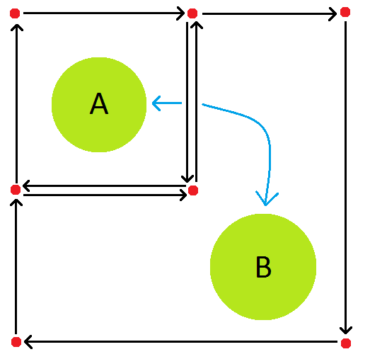
Overlapping
Here we have another clearly broken situation - the larger face overlaps the smaller face. In this case the solution is quite obvious from the image - the grey edges are already in use for the smaller face so we can’t possibly assign them to the larger face!
These Vertices Were Made For Walking
Let’s have a look at the most simple query you can perform: finding all the vertices around a face. With an indexed mesh this is obviously rather trivial:
for (index in face)
    yield vertices[index]
This is pretty much exactly what an indexed mesh is designed for! With a half edge mesh this is slightly more complex. The half edges around a face all point to the next half edge around the same face, in this way they form a circular singly linked list around the face. Additionally a face points to an arbitrary bordering edge. These two pieces of information are all you need:
first = face.edge
edge = first
do
{
    yield edge.EndVertex
    edge = edge.Next
} while (edge != first)
Just keep following those “next” pointers until we get back to where we started!
Many queries can be implemented on a half edge mesh using the same concept - just keep chasing pointers! For example let’s say we want to find all neighbouring faces to a given face. With an indexed mesh this is a nightmare:
# assume we have a variable "face" which is the start of the query
for (neighbour in faces)
    if (neighbour == face)
        continue;
    for (var i = 0; i < neighbour.Length; i++)
        find = face.IndexOf(index)
        if (find != -1 && face[(find + 1) % face.Length)] == neighbour[(i + 1) % neighbour.Length])
            yield neighbour;
I’m not certain that’s correct (it’s just blog pseudocode, gimmie a break) but essentially what I’m doing here is enumerating all vertices of all other faces and trying to find pairs which are in the query face, but reversed. I’ve almost certainly got some off-by-one errors here, and looking back on it I think I’ve got one of the indices the wrong way around. The point is this is annoying code to write and, even worse, the algorithmic complexity is horrible - something like O(#Faces * #AvgVerticesInFace).
Here’s how we do the same thing with a half edge mesh:
first = face.edge
edge = first
do
{
    if (edge.Sibling.Face != null)
        yield edge.Sibling.Face
    edge = edge.Next
} while (edge != first)
I hope you’ll agree that’s much friendlier and far easier to read! All we’re doing here is enumerating the edges around the face (in the exactly same way we did in the previous example) and then jumping across to the sibling edge and getting the attached face. This was really easy to write and is far less algorithmically complex - O(#EdgesInThisFace).
A few more of the queries which can be done easily in a half edge mesh:
- Edges around face
- Vertices around face
- Faces around face
- Edges from vertex
- Faces around vertex
- Pathfinding (and other graph based algorithms)
If you can’t figure out how to implement some of these queries post a comment below and I’ll do another post explaining them in more detail!
How Does This Help?
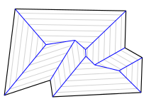
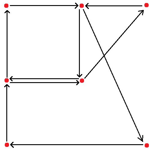
Here’s a concrete example of how these kinds of queries can help - we can use them to detect even more invalid geometry (winding order, overlapping and self-intersection). Let’s look at the overlapping case, here’s a nasty piece of overlapping geometry which would not be detected normally:
This overlap doesn’t generate any invalid edges and would likely never be detected by the normal checks. However, if we can do intersection checks (just normal 2D collision detection) we can check for this situation quite easily:
for (vertex in face)
    for (neighbour in vertex.Faces())   # <-- .Faces() is the query
        if (face.Intersects(neighbour))
            throw new InvalidMeshException("Oh no!");
Pretty simple - we just query every vertex in the proposed new face for neighbours and then check if we overlap any of those faces. This won’t catch all invalid overlaps but, as with many of these checks, it ratchets up the difficulty of accidentally creating invalid geometry.
Conclusion
Half Edge meshes are a more powerful way to represent meshes than a traditional indexed mesh. I use them as the basis for many of my procedural generators where they help ensure that the generator can only ever generate valid geometry.